
Overview
This document summarizes high-level design recommendations and best practices for implementing IP Video Surveillance on the enterprise network infrastructure. In some instances, existing network equipment and topologies have the necessary configuration and performance characteristics to support high-quality IP Video Surveillance. In other instances, network hardware might require upgrading or reconfiguration to support increased bandwidth needed to support video. Quality-of-service (QoS) techniques are important for any design because video has similar—in some instances, more stringent—requirements than VoIP for loss, latency, and jitter.
IP Video Surveillance is a part of the Media Ready Network—a network initiative to incorporate all forms of video on the enterprise network. IP-based Video Surveillance is one of the four components of the Media Ready Network. These components consist of the following:
• TelePresence Network System
•Desktop Video
•Digital Media Systems
•IP Video Surveillance
This solution overview focuses on IP Video Surveillance while other overviews focus on the other three solutions. Not all forms of video on the enterprise network have the same requirements, given the diversity of transport techniques and user interfaces to the video feeds.
IP Video Surveillance Components
There are five components of IP-based video surveillance solution. These are as follows:
•Cameras—This is addressed by the Cisco Video Surveillance IP Camera, analog cameras attached to encoders, analog gateway network modules for the integrated services router, or third-party IP surveillance cameras.
•Video management software—This is addressed by the Cisco Video Surveillance Manager (VSM) suite of software. This software runs on one or more standalone, Linux-based servers or on a Cisco Integrated Services Router (ISR) Series Video Management and Storage System network module.
•Servers- Cisco Physical Security Multi Services Platforms are servers for network digital recording and playback.
•Storage—This is aligned with either the Data Center Architecture and the Cisco Video Surveillance Storage System, or with off-the-shelf iSCSI servers for archiving and storage of video feeds
•Network—This component is the enterprise network—the Media Ready Network. The primary focus of this document is to reference the existing design baselines of branch office, campus, WAN, and Metro Area Networks (MANs) while building on this base of knowledge with IP Video Surveillance requirements, best practices, and design recommendations.
The IP Video Surveillance component of the Media Ready Network is integrated with the Places in the Network (PIN) architecture along with the companion video components of the Media Ready Network.
Supporting Designs
Implementing IP Video Surveillance on an existing network is designed to overlay non-disruptively on other core Cisco PIN architecture design elements. These include the following:
Each is summarized in the following subsections.
Quality of Service Design Considerations
QoS design is addressed in the Enterprise QoS Solution Reference Network Design Guide Version 3.3 available at the following URL:
and should be considered a fundamental consideration for implementing video on any corporate network. Both voice and video are tolerant of some packet loss, latency, and jitter between the video end points; however, video is typically less tolerant to loss than voice over IP (VoIP). Depending on the type of video feed, the disruption of video quality might be evident for much longer periods of time than with VoIP.
Branch PIN Design Considerations
The branch architecture design collateral is organized under the Design Zone for Branch, which can be found at the following URL:
From this website, there are a number of branch-related PIN design guides that are applicable to implementing a branch router deployment. They include the following:
•Enterprise Branch Architecture Design Overview
•Enterprise Branch Security Design Guide
•Enterprise Branch Wide Area Application Services Design Guide (Version 1.1)
The integration between IP Video Surveillance and the enterprise branch architecture is targeted at integration of the Cisco ISR VS network modules. Enabling branch architecture services along with the Cisco ISR VS network modules is a key element of IP Video Surveillance 1.0.
The Cisco Empowered Branch 4 marketing launch included the Cisco Video EVM-IPS-16A EVM Module featuring analog-to-IP encoding capabilities for existing analog cameras and the Cisco NME-VMSS Module that supports the Cisco Video Surveillance Manager (VSM) suite of software on the network module. The EVM-IPS-16A module is not required if the deployment is with all IP surveillance cameras.
Empowered Branch 4 also includes the Cisco 880 ISRs, which have sufficient performance characteristics to support the various forms of video at a Small Office/Home Office (SOHO) location. Many of the foundation architecture concepts are from the Business Ready Teleworker.
The teleworker or SOHO deployment is applicable for addressing remotely located or isolated wired-IP cameras that in turn can be managed by a central or branch Video Surveillance Manager deployment. Video Surveillance Operations Manager viewing stations—PCs running an Active-X-enabled web browser—may also be located at extranet or remote locations to allow physical security staff or law enforcement agencies to view live or archived video.
The Cisco Application Networking Services (ANS), such as Wide Area Application Services (WAAS), are key elements given that the transport for IP Video Surveillance viewing stations is TCP-based.
WAN/MAN PIN Design Considerations
The WAN/MAN PIN architecture reference is found at the following URL:
There are several design guides within the Design Zone for WAN/MAN that describe foundation architectures for deploying IP Video Surveillance. The integration between IP Video Surveillance and the WAN/MAN architecture is targeted at QoS, NetFlow, Network-Based Application Recognition (NBAR), Ethernet access, Performance Routing (PfR), and implementing IP Security (IPSec) technologies to enable privacy, integrity, and authenticity of IP Video Surveillance data through encryption. Because of the focus on the Cisco ISR VS network modules in branch routers, the design guidance provided here relies heavily on integration of the WAN/MAN PIN.
If the branch office locations are implemented over a public network, the Dynamic Multipoint VPN (DMVPN) Design Guide provides important information on encrypting data between branch, SOHO, and central office locations. Because of the requirements for availability and selecting the optimal path among redundant links, the Transport Diversity: Performance Routing (PfR) Design Guide is also a key element in a successful deployment. Video requires much higher bandwidth than is required for a VoIP and data enabled branch location and the Ethernet Access for Next Gen Metro and Wide Area Networks might be applicable when implementing the branch office over a Metro Ethernet deployment or an Multiprotocol Label Switching (MPLS) Layer-2 pseudowire. Also applicable is the Next Generation Enterprise MPLS VPN-Based MAN Design and Implementation Guide.
Campus PIN Design Considerations
The campus PIN architecture reference is found at the following URL:
There are several design guides within this Design Zone for Campus that can provide guidance to the network manager in designing a Media Ready campus. These include the following:
•Network Virtualization—Path Isolation Design Guide
•Network Virtualization—Services Edge Design Guide
•Campus Network for High Availability Design Guide
•Campus Design: Analyzing the Impact of Emerging Technologies on Campus Design
The integration between IP Video Surveillance and campus PIN architecture is a requirement because most IP network cameras support Power-over-Ethernet (PoE). PoE is important to facilitate installation of these cameras as a single Category 5 Ethernet cable can provide both Ethernet connectivity and power-reducing installation costs. The Cisco IP cameras support Cisco Discovery Protocol (CDP) and Simple Network Management Protocol (SNMP), which together help to simplify provisioning and device management.
In the campus, QoS marking at both Layer 2—class-of-service (CoS) and Layer 3—Differentiated Services Code Point (DSCP)—can be enabled in the switching infrastructure to enhance the usability and quality of the video feeds.
The cameras, servers, and encoders can be deployed on separate VLANs to provide isolation at Layer 2 and transported over the WAN with Layer-3 isolation over an MPLS virtual private network (VPN).
Data Center PIN Architecture
The data center PIN architecture reference links can be found within the Design Zone for Data Center at the following URL:
The integration between IP Video Surveillance and the Data Center PIN Architecture intersects notably at the storage requirements of an IP Video Surveillance system. An archive is a collection of video data. The video source, a feed from a camera or encoder, can be stored in multiple locations and viewed at a later time. Archives are either one-time (where the archive recording stops at a specified date and time) or continuous loop (where the archive continuously records). Loop archives reuse the disk space. Archives may also be scheduled to begin at a certain date and time and run using a recurring schedule.
The storage requirements for video archives can be substantial. For example, a high definition (HD) surveillance camera recording at a rate of 10-motion JPEG frames per second with a resolution of 1600 x 1200 pixels can require up to 1GB of disk storage per hour. Retention of this archive for days or weeks, combined with a deployment of a hundred cameras will consume vast amounts of storage.
The Cisco Video Surveillance Manager Solutions Reference Guide addresses at a functional level the way in which the storage subsystem of the Cisco Video Surveillance Media Server can augment internal storage with direct-attached storage and storage area networks (SANs). Additionally, the Cisco ISR Series Video Management and Storage System network module supports an iSCSI interface for local storage in the branch office.
Technical Assistance Center (TAC
Technical Assistance Center (TAC) Technical Tips are a valuable sources of configuration examples for the technologies deployed in this design guide. Refer to the Technical Tip section after logging on the Cisco TAC website at http://www.cisco.com/tac.
Solution Description
In this section the, Cisco Video Surveillance solution is described at a functional-level given a deployment of the components on standalone workstations and appliances. In addition, the functional components are mapped to an implementation using the Cisco 2800/3800 ISR IP Video Surveillance Network Modules. The Cisco Video Surveillance Manager software is a common code base that is ported to run on the network module.
Cisco Video Surveillance Solution
The Cisco Video Surveillance solution relies on an IP network infrastructure to link all components. The designs of a highly available hierarchical network have been proven and tested for many years and allow applications to converge on an intelligent and resilient infrastructure.
Cisco offers a unique approach to moving different proprietary systems to a common IP backbone. This approach uses other Cisco technologies, such as network security, routing, switching, network management, and wireless. Video from IP cameras can now be truly converged into a robust network environment with the intelligence and flexibility provided by the Cisco infrastructure.
Figure 1-1 shows the Cisco Video Surveillance Manager solution using an Intelligent IP infrastructure as a transport.
Figure 1-1 Cisco Video Surveillance Solution

Solution Components
The Cisco Video Surveillance solution components are as follows:
•Cisco Video Surveillance Media Server—As the core component of the network-centric VSM, this software manages, stores, and delivers video for the network-centric video surveillance product portfolio.
•Cisco Video Surveillance Operations Manager—The Operations Manager authenticates and manages access to video feeds. It is a centralized administration tool for management of Media Servers, Virtual Matrixes, cameras, encoders, and viewers—and for viewing network-based video.
•Cisco Video Surveillance Virtual Matrix—The Virtual Matrix monitors video feeds in command center and other 24-hour monitoring environments. It allows operators to control the video being displayed on multiple local and remote monitors.
•Cisco Video Surveillance Encoding Server—This single-box solution encodes, distributes, manages, and archives digital video feeds. Each server encodes up to 64 channels and provides up to 12 TB of storage.
•Cisco Video Surveillance Storage System—This complementary component allows the Media Server's internal storage to be combined with direct-attached storage (DAS) and storage area networks (SANs). The storage system allows video to be secured and accessed locally or remotely.
Cisco 2800/3800 ISR IP Video Surveillance Network Modules
In addition to the standalone dedicated implementation of the Cisco Video Surveillance solution on Linux servers, the Cisco 2800 and Cisco 3800 ISRs support the necessary components of the solution to implement a self-contained instance at the branch location.
The Cisco Video Management and Storage System (VMSS) Network Module implements the Operations Manager and Media Server functions for the branch. It supports IP-based video cameras as well as analog cameras attached to the Analog Video Gateway Module.
The Analog Video Gateway Module installed in the Cisco ISR branch router provides support for analog cameras, analog Pan Tilt Zoom (PTZ), alarm input and control relay output. It supports up to 16 analog cameras. This module supports RS-485 on two serial interfaces, which controls analog Pan Tilt Zoom (PTZ). The module also supports event alerts by way of alarm input and control-relay output serial connections. The Analog Video Gateway Module is optional if these functions are not required.
A branch with all IP cameras and no analog requirements need only the VMSS network module. The NME-VMSS-16 and NME-VMSS-HP16 support up to 16 cameras, the NME-VMSS-HP32 is licensed to support up to 32 cameras.
The Virtual Matrix component is not supported on the Cisco ISR Video Surveillance Modules.
The Operations Manager provides a web-based browser console to configure, manage, display, and control video supported at the branch location. The Operations Manager and the Media Server share the same IP address configured on the logical interface of the Integrated Services Network Module. One or more Cisco Video Surveillance Media Servers are managed through this interface. The Operations Manager web interface is where the physical security administrator configures IP and analog cameras and where video feed archives are scheduled and managed.
In this remote branch location deployment, use of the Cisco VMSS provides efficiency. Traffic only needs to traverse the network when requested by remote viewers. Branch office video remains localized and does not have to traverse wide-area connections unless requested by users. An external iSCSI device is attached to the GigabitEthernet port on the network module in order to supplement the disk storage on the VMSS module.
In this topology, physical security staff at the campus location, a third-party location at an Extranet site, a separate branch, or even a remote teleworker location can configure, manage, and display the VMSS at the branch location. Video requests and video streams are delivered to the viewer through Hypertext Transfer Protocol (HTTP), which uses Transmission Control Protocol (TCP) port 80.
In Figure 1-2, the Video Surveillance Manager Software Suite components for both the Linux deployment and the Cisco ISR IP Video Surveillance Network Module deployment are shown.
Figure 1-2 Video Surveillance Manager Software Suite Components
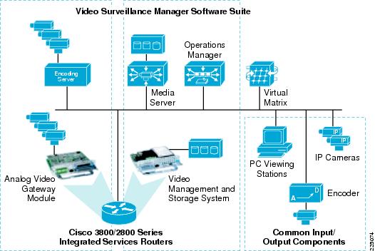
At the branch location, the Analog Video Gateway Module provides a similar function to the encoding server. The Media Server and Operations Manager, along with storage, are supported on the VMSS network module. The Virtual Matrix function is not supported on the Cisco ISR Video Surveillance Modules. The IP cameras, analog cameras attached to dedicated IP encoders, and the PCs used as viewing stations are common to both implementations.
Solution Benefits
Video surveillance is a key component of the safety and security procedures of many organizations. It provides real-time monitoring of the environment, people, and assets, and provides a recorded archive for investigative purposes. The benefits of Cisco's Video Surveillance solution include the following:
•Provides access to video at any time from any network location within the constraints of available bandwidth, allowing remote monitoring, investigation, and incident response through remote physical security staff or law enforcement personnel.
•Uses existing investment in video surveillance and physical security equipment and technology.
•Network-wide Management—IP cameras and servers are monitored and managed over a single network for fault, configuration, and centralized logging.
•Increased Availability—IP networks offer a high level of redundancy that can extend to different physical locations.
•Scalability—The system can be expanded to new locations as business needs change.
•Digitized images can be transported and duplicated worldwide with no reduction in quality, economically stored, and efficiently indexed and retrieved.
•Employs an open, standards-based infrastructure that enables the deployment and control of new security applications from a variety of vendors.
•The Cisco Video Surveillance Solution relies on an IP network infrastructure to link all components, providing high availability, QoS, performance routing, WAN optimization, and privacy of data through IPSec encryption.
Understanding the key steps in the website development process can help you build better, faster, and more efficient websites. Whether it’s wireframing, coding, or testing, following a structured approach is essential. For a complete breakdown, visit CodeZion’s comprehensive guide on the website development process. It’s a must-read for developers and designers alike!
ReplyDeleteStay ahead in the game with Khelbazar.online! Get the latest sridevi night panel chart and make informed decisions with accurate insights. Whether you're tracking trends or planning strategies, we provide reliable updates. Don’t miss out—visit us now for expert analysis and real-time results!
ReplyDelete