Solution Overview and Best Practices
This chapter presents a high-level overview of an IP Video Surveillance deployment to give the reader a quick reference as to the capabilities of this solution. The associated design guide will then go into detail on planning, design, product selection, and implementation of an IP Video Surveillance deployment.
Deployment Model
A typical IP Video Surveillance deployment in an enterprise network consists of one or more campus locations running Cisco Video Surveillance Media Server, Video Surveillance Operations Manager, and Video Surveillance Virtual Matrix on an Intel-based Linux Enterprise Server operating system (Cisco Physical Security Multi Services Platform or third party server). Deployment on a standalone hardware is targeted at locations with more than 32 video surveillance cameras.
Branches that have a requirement for 1-to-32 video surveillance cameras can incorporate the Cisco ISR Video Surveillance Modules to provide the Media Server and Operations Manager functionality in a network module form factor. Optionally, an Analog Video Gateway Module can be installed to support legacy analog cameras.
Branch offices and teleworker locations may view and administer the video surveillance system—as may external organizations connected either through an Extranet or the public Internet through a global IP connectivity and a web browser.
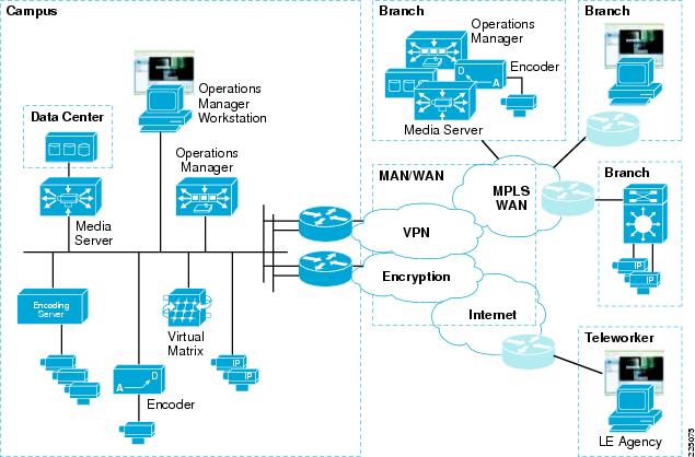
Figure 2-1 illustrates the topology and application services deployed in an enterprise-wide implementation of IP-based video surveillance.
Figure 2-1 Video Surveillance Solution Master Architecture Diagram
The branch locations are connected to the enterprise campus by WAN technologies, including Metro Ethernet, private line, the public Internet, or a Layer-2 or Layer-3 MPLS VPN deployment. With a Layer-2 MPLS deployments (Pseudowire), IP cameras may be Ethernet-attached to a remote switch and have images transported through the carrier network and provisioned and managed by the Operations Manager at either a branch location or a central location. Branches attached through a Layer-3 MPLS network, leased line, or over the Internet can support viewing stations and IP cameras that can be managed by either the campus or branch deployment.
Cisco technologies such as DMVPN can be overlaid onto the WAN transport to provide data privacy and authentication by way of IPSec encryption. To ensure prioritization of voice, video, and mission critical applications over the WAN, QoS is deployed on the WAN. Where multiple WAN links exist, PfR can be enabled to provide intelligent path selection and the ability to route around brownouts and transient failures, thereby enhancing what can be provided by traditional routing protocols such as Enhanced Internal Gateway Routing Protocol (EIGRP).
The decision as to whether a specific environment should implement the Cisco ISR Video Surveillance Modules at a branch location and archive data at the branch—or provision cameras off the campus implementation of the Cisco Video Surveillance Manager—depends on the number of cameras, the resolution, frame or bit rate of the camera, quality factors of the cameras, and the cost and availability of bandwidth at the remote locations. In cases where implementing cameras is the only requirement, it may be practical to transport the camera feeds across the WAN for archiving. However, in most deployments, local storage is necessary due to the bandwidth required and the costs associated with this bandwidth.
Solution Characteristics
Table 2-1 represents the general solution characteristics for an IP Video Surveillance deployment.
Table 2-1 Solution Characteristics Summary
Solution Characteristics
|
|---|
An IP network infrastructure is required to link all components.
|
IP cameras are under the control of and feed Media Servers. The VSOM interface is the viewing station portal into the video archives and live feeds.
|
The amount of disk storage for archiving camera feeds depends on factors that include the retention period requirements, image resolution, image quality, format , and encoding. Storage requirements might be difficult to plan and predict.
|
Encryption through IPSec may be implemented between video endpoints to ensure data privacy, integrity, and authentication.
|
VRF-lite, VLANs, and other network virtualization techniques may be used to segment the video endpoints and servers.
|
Viewing stations are PCs running Internet Explorer (IE) with Active-X controls. The PC must have a sufficient CPU clock rate to decode the video feeds.
|
Camera feeds traverse the IP network from the camera source to the Media Server either as Motion JPEG (MJPEG) or MPEG-4.
|
MJPEG is typically transported via the TCP protocol. TCP provides guaranteed delivery of packets by requiring acknowledgement by the receiver. Packets that are not acknowledged are retransmitted.
|
With MJPEG, each image standalone, so the images that are displayed are of good quality.
|
MPEG-4 video is typically transmitted over the User Datagram Protocol (UDP), Real-time Transport Protocol (RTP), or Real Time Streaming Protocol (RTSP). UDP does not guarantee delivery and provides no facility for retransmission of lost packets.
|
UDP transport provides the option of IP Multicast (IPmc) delivery, however is not universally supported.
|
Deploying a video surveillance solution through a WAN environment presents challenges that are not typically seen in a LAN. WAN bandwidth is most costly and the available transport types are dependent on the service provider offering available in the geographic area.
|
General Best Practices Guidelines
Table 2-2 presents a list of best practices that have been established through a combination of design experience, scalability and performance evaluation, and internal Cisco trials.
Table 2-2 IP Video Surveillance Best Practices Guidelines Summary
Best Practices Guidelines
|
|---|
Network Time Protocol (NTP) must be configured for an accurate and consistent time source for all video surveillance devices in the network.
|
Camera feeds for MJPEG can be reduced to save bandwidth and disk storage. For example, 30 frames per second (fps) can be configured from camera to Media Server, while two archives for this feed can be configured; one at 10 fps and a second at 1 fps. These archives can have different retention periods.
|
Access control techniques to limit the workstations that are allowed to configure and view an IP camera directly should be implemented.
|
Where possible, use PoE for IP cameras. It simplifies installation.
|
IP Video Surveillance traffic is to be marked with the QoS DSCP value of CS5 and provisioned in either a priority or bandwidth queue.
|
Cisco IP Video Surveillance (IPVS) Utilities for the Cisco ISR Analog Gateway Module can be accessed with the following URL:http://ipaddress/ipvs/login.html, where ipaddress is the IP address of the analog network module. This utility facilitates implementation of analog cameras, RS-485 devices, alarms, and contract relays.
|
In most instances, configuring a camera feed constant bit-rate (CBR) value of 1024Kbps is an acceptable starting value for reasonable video quality.
|
Most implementations will require at least 4CIF or D1 video resolution for reasonable video quality.
|
MPEG-4 over RTP/UDP is relatively intolerant to packet loss; however, latency and jitter cause less degradation because the Media Server functions as a dejitter buffer (due to the storage and replication of the camera feed to the viewing station). Manage WAN links to minimize loss, even at the expense of latency and jitter. Round Trip Times (RTT) of 300 msec might be acceptable.
|
Latency between client viewing station and VSOM should be less than 80 msec RTT for best results.
|
Many IP cameras can be configured as both MJPEG or MPEG-4 codec technology. Both have advantages and disadvantages. A mixture of these codecs on certain cameras might be desirable.
|
In most instances, the only manual CLI configuration required on the Cisco ISR Analog Gateway Module would be text descriptions of the physical ports. VSOM will provide all the configuration necessary for operation of this module when adding cameras or alarm events.
|
General Solution Caveats
Table 2-3 presents a list of caveats for the solution described in this solution overview.
Table 2-3 IP Video Surveillance Solution Implementation Caveats
Solution Implementation Caveats
|
|---|
The available disk storage for video archives on the Cisco ISR Video Surveillance Modules is approximately 100 GB. In most deployments, external disk archives storage is required.
|
Not all features of the Cisco 2500 Series Video Surveillance IP camera are supported by Cisco VSM. For example, the IP camera supports IP multicast, but VSM does not. QoS can be enabled on the IP camera by configuring the camera directly through a supported web browser, but the QoS parameters cannot be configured from VSM.
|
Some HD cameras only support the higher definition resolution on MJPEG.
|
The latency of video encoders used in some IP cameras might exceed 500 msec, and values of 2,000 to 3,000 msec have been observed. This presents usability issues when using the audio and speaker jacks of the camera or with PTZ controls.
|
When defining analog cameras under VSOM using the Cisco ISR Analog Gateway Module, the Encoder Channel field is not zero relative. In other words, Encoder Channel 1 is coax cable 0 on the CAB-EVM-IPVS-16A.
|
When defining alarms/control relay events in the Cisco ISR Analog Gateway Module, VSOM port COM1 equates to S0, while COM2 equates to S1. Contact closure port 0 equates to Channel 1in VSOM.
|
When defining PTZ analog cameras in VSOM, Chain Number equates to the RS-485 address switch value on the camera.
|
When defining Bosch Autodome analog cameras with PTZ on the Cisco ISR Analog Gateway Module, use Pelco Analog Camera (D protocol) rather than selecting Autodome Analog Camera.
|
The PTZ analog device is intermittently unresponsive to joystick movements from the Video Surveillance Operations Manager (VSOM). See CSCsk21927.
|
Symptom—Video image does not load on the upper first pane on various layouts with VMR enabled.
Workaround—Disable VMR mode in the VSOM under Settings if this problem occurs.
|
In some instances, there may be a delay of several seconds, up to a minute, from the time an operator selects a camera feed to view, until the video feed is displayed. It may require several mouse clicks on the camera feed to initiate viewing.
|
Cannot configure VSVM on the Cisco ISR Video Surveillance Modules. Error "Cannot connect to server at 192.0.2.2:8086" is displayed. VSVM is not supported on the network module implementation.
|
There are incompatibility issues when a NAT/pNAT device is located between the client viewing station and the VSOM.
|
In VSOM, previews are displayed when you configure JPEG but not with MPEG-4.
|
Recurring archives might stop initiating if the disk media becomes full.
|
This is a short description in the author block about the author. You edit it by entering text in the "Biographical Info" field in the user admin panel.

0 comments:
Post a Comment